Parts 1-4 of this series presented a refresher course in dealing with wind farm and point-to-point telecommunications issues, a recap on understanding the interference mechanisms, a presentation of a photographic encyclopaedia of telecommunications equipment and details regarding the stakeholder consultation process. Part 5 of this series presents an example fictional study, following the assessment process whereby Pager Power has proposed a wind turbine in the immediate area surrounding the office.
The Proposal
Pager Power is ‘proposing’ the development of a wind turbine in a field adjacent to Pager Power’s office complex. The wind turbine will have a hub height of 150m above ground level and a rotor diameter of 150m. The overall tip height of the wind turbine will be 225m above ground level.
The Telecoms Infrastructure
Pager Power has consulted the relevant telecommunications stakeholders. In this instance, one microwave link was identified (link reference: Sudbury – Babel Green), which operates between the Sudbury television mast, and a mast near the village of Babel Green. Co-ordinates and elevations were provided for each link end (the dish which sends and receives the signal), as well as the link frequency (10GHz).
Pager Power also identified a mast on the roof of one of the office buildings in the office complex.
No other infrastructure was identified for the purpose of this example study.
Mapping of the Wind Turbine and the Identified Infrastructure
The location of the wind turbine relative to the identified infrastructure is presented in Figure 1 below. The Sudbury – Babel Green Green link is denoted by a blue line representing the direct pathway (boresight) between the two masts.
Figure 2 shows a zoomed map of the wind turbine and mast.
Figure 1 – Map showing proposed wind turbine and identified telecoms infrastructure.
Figure 2 – Zoomed map showing proposed wind turbine and identified telecoms infrastructure.
2-Dimensional Clearance Analysis
Two-dimensional Fresnel zone analysis was undertaken for the identified Sudbury – Babel Green link and the 2D clearance sheet is presented below. The sheet is designed to give developers (and stakeholders) key information about the development environment, with the most important figure being the clearance or infringement relative to the wind turbine.
Figure 3 – 2D Fresnel zone analysis calculation sheet.
In this instance, the clearance between the tip of the rotor blade and the 2nd Fresnel zone is 172.6m. This figure includes an additional clearance of 25m, which is typically included to account for micrositing uncertainties in both the turbine and mast locations. Where more accurate figures are known, reassurances are offered or a survey has been undertaken, this distance can be reduced. In some cases where the turbine lies close to an exclusion zone but is otherwise acceptable, restrictions on turbine micrositing may be required to ensure there is no encroachment into the exclusion zone.
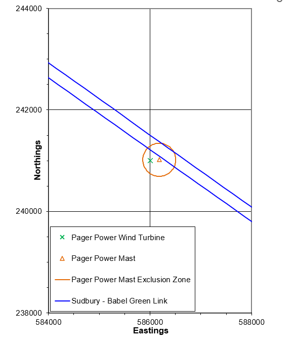
Figure 4 below shows the 2D exclusion zone chart.
The green cross denotes the location of the proposed wind turbine.
The blue lines denote the exclusion zone for the Sudbury – Babel Green link path. This zone consists of the rotor radius, 2nd Fresnel zone and 25m buffer. The rotor radius is included because the specific location of the turbine (green cross) can then be relocated without there being a question of the rotor radius infringing the exclusion zone.
The chart also shows a 250m exclusion zone (orange circle) around the nearby mast (orange icon). This zone is initially established around masts to avoid the possibility of nearfield effects caused by the presence of the wind turbine in proximity to transmitting antenna.
Figure 4 – 2D Fresnel zone analysis clearance chart.
The chart shows, as per the calculation sheet, that the proposed turbine is outside of the exclusion zone associated with Sudbury – Babel Green link. The turbine would however lie within the 250m exclusion zone, which is initially cited to avoid nearfield effects. Like the link path analysis, the mast exclusion zone also considers the rotor radius. If this wind development were to proceed, this is something that would have to be considered further.
3-Dimensional Clearance Analysis
For completeness, 3D clearance analysis was completed for the Sudbury – Babel Green link. The difference in 3D will always be greater than in 2D unless the link path passes the wind turbines at the exact same elevation of the turbine’s hub – this is very unlikely. In some cases, the additional clearance in 3D can make all the difference between infringing or clearing the link exclusion zone. In this instance, the 3D clearance is 178.2m (as opposed to 172.6m in 2D).
Figure 5 – 3D Fresnel zone analysis calculation sheet.
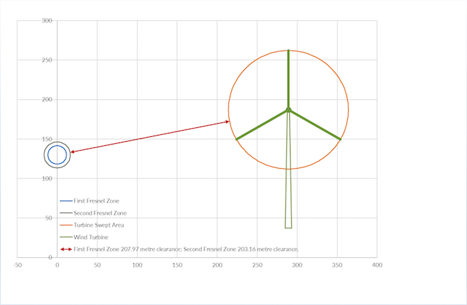
Figure 6 below shows graphically the clearance between the link path and the turbine. No additional clearance is included within this figure so the figures stated are 25m bigger.
Figure 6 – 3D Fresnel zone analysis clearance chart.
Conclusions
The analysis in this example study has shown the proposed wind turbine would be clear with respect to the Sudbury – Babel Green link, and this conclusion would need to be confirmed with the stakeholder. The presence of the wind turbine within the 250m mast exclusion zone would require further consideration, with questions needing to be posed to the stakeholder regarding the mast’s usage and tolerance to change. Further analysis would likely then be proposed.
Overall, the aim of this study was to show a few of the tools Pager Power has at its disposal to assist developers with telecommunication planning issues. Many are bespoke and can be amended and optimised to meet many different requirements. If you have any telecommunications planning issues, however niche, please get in touch.
Additional Resources
Further information on communications issues surrounding wind farms can be found in the following articles:
- Refresher Course in Wind Farms and Point-to-Point Telecoms Issues – Part 1 – Overview
- Refresher Course in Wind Farms and Point-to-Point Telecoms Issues – Part 2 – Interference Mechanisms
- Refresher Course in Wind Farms and Point-to-Point Telecoms Issues – Part 3 – Photographic Encyclopaedia
- Refresher Course in Wind Farms and Point-to-Point Telecoms Issues – Part 4 – Stakeholder Consultation
- Communications planning issues for wind turbines
- What is a Fresnel zone
- Wind turbine terrestrial television interference
Click here to read the next article in this series, which includes a list of key facts and takeaways that you should know about developing in the presence of point-to-point telecommunications infrastructure, and this will include FAQs.


