What is a Fresnel Zone?

Last Updated: June 19, 2020
Categories:
Share:
Wireless Links
Wireless communication systems are ubiquitous throughout the UK and many other countries. Typical uses include mobile phone networks, whereby individual masts are connected to the wider network via point-to-point communication links.
Interference
Links between two antennae function best with a clear, unobstructed [1] path between each end. Structures located between transmitters and receivers have the potential to corrupt or block the transmitted signal.
Potential interference from terrain, vegetation, buildings, wind farms and a host of other obstructions must be considered when designing and maintaining wireless communication systems.
This article focusses on the effects of signal blocking, which is formally known as ‘diffraction’ in this context. Other interference mechanisms include reflection of the transmitted signal, and emissions issues from electronic equipment. These issues are not discussed here.
Safeguarding
The straight line between a transmitter and a receiver is known as the link boresight. If a structure is placed in such a way that it infringes the boresight, high diffraction losses can occur. An obstruction that is close to – but not infringing – the link boresight can cause lower losses. The question is: how close is too close?
The answer depends on:
- The link type (length, frequency, function etc).
- The obstruction (terrain and wind turbines may be treated differently).
However, under most circumstances, safeguarding is achieved by considering Fresnel Zones.
Fresnel Zones
A Fresnel Zone is a cigar-shaped area, in three dimensions, centred on a link boresight. The figure below illustrates this.
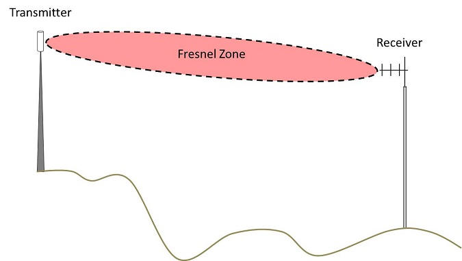
Figure 1: Fresnel zone illustration.
It can be seen that the Fresnel Zone is widest in the middle and narrowest at the ends. The Fresnel Zone radius, along with the formula for calculating it, are shown in the figure below.
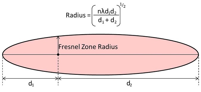
Figure 2: Fresnel zone radius.
The radius is dependent on:
- The length of the link.
- The distance along the link path.
- The frequency of the link.
- The Fresnel Zone number ‘n’ – which is a number greater than zero.
Freznel Zone number ‘n’
Common values of n used in practice include 0.6, 1, 2 and 8. The latter can also be referred to as the first, second or eighth Fresnel Zone. The 0.6 Fresnel Zone is often applied when designing point to point telecommunications links over terrain and vegetation and the second Fresnel zone is usually used for safeguarding telecommunications links from potential interference from wind turbines.
At any point along the link path the Fresnel zone radius is proportional to the square root of n. This means that if you no the radius of one Fresnel zone you can work out the radius of another relatively easily. The eighth Fresnel Zone radius is twice the second Fresnel Zone radius because the square root of eight divided two (four) is two.
Why does it matter?
Structures that infringe Fresnel Zones can adversely affect the link’s performance. This can lead to objections in the pre-planning stage of a development and mitigation requirements.
Understanding the extent of the Fresnel Zones gives developers a good sense of whether interference issues are likely. The figure below illustrates this concept using two wind turbines, with identical dimensions, beneath the link path illustrated in Figure 1. This principle applies to other constructions such as buildings as well.
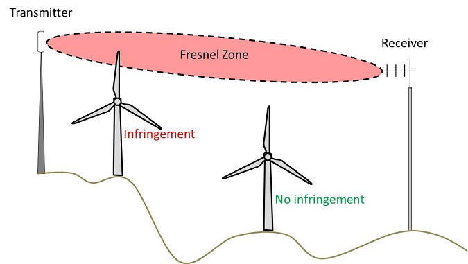
Figure 3: Fresnel zone importance.
Footnote
[1] There are instances whereby an obstructed path can be accommodated by a system. This is typically more true of UHF systems than higher frequency links.
References
- Bacon (2002): A proposed method for establishing an exclusion zone around a terrestrial fixed radio link outside of which a wind turbine will cause negligible degradation of the radio link performance.
- Joint Radio Company (2009): Calculation of Wind Turbine clearance zones for JRC UHF (460MHz) Telemetry Systems when turbine sizes and locations are accurately known.
- Manning (1999): Microwave Radio Transmission Design Guide, Artech House.
post contents
About the Author: Kai Frolic
Latest News

Onward 2030 Work Package 2: What do developers need to know about Instrument Flight Procedures (IFPs)?
What are the Onward 2030 Work Packages? Onward 2030 has [...]

UK Onshore Wind: Why Invest in Repowering?
There is currently 316 MW of operational onshore wind capacity [...]

What Happens if I Submit a Wind Turbine Planning Application Without an Aviation Assessment?
Planning applications for wind developments consider many aspects to ensure [...]


