New ICAO OLS Series – The Instrument Departure Surface

The International Civil Aviation Organization (ICAO) has proposed new Obstacle Limitation Surfaces (OLS) which are expected to be brought into force from November 2028. In this edition we will explore the Instrument Departure Surface. This will be an Obstacle Evaluation Surface (OES), designed specifically to safeguard instrument departures to allow for instances in which the rules around the Take Off Climb Surface (TOCS) are not stringent enough.
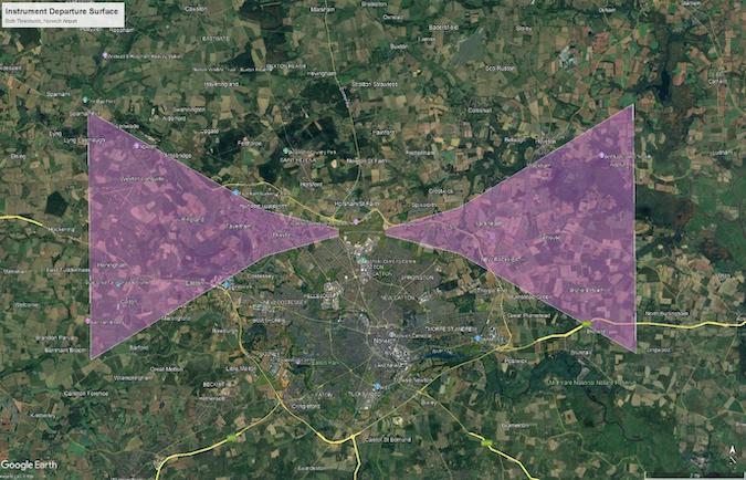
Figure 1: Pager Power modelling output for a potential Instrument Departure Surface at Norwich Airport Runway 27, overlaid on Google Earth imagery. This figure is given for illustrative purposes only [1].
What is the difference between OFS and OES?
The new OLS is expected to be split into two types of surfaces. The OFS aim to protect airspace in the immediate vicinity of the aerodrome, and will provide protection for all designated airspace that aircraft will travel through or near when arriving or departing. The rules are expected to be enforced quite rigidly, with 4.4.4 of the ICAO State letter [2] stating that:
“New objects or extensions of existing objects shall not be permitted above the approach surface, take off climb surface and transitional surfaces and the complex surface extending between the lower edges of the transitional surfaces [obstacle free surfaces].”
This places an effective ban on any new obstructions breaching the OFS. The Instrument Departure Surface is however one of the surfaces with less strict criteria governing its safeguarding, with paragraph 4.4.8 [2] stipulating:
“States shall ensure that obstacles penetrating the obstacle evaluation surfaces are only permitted when, after aeronautical study, it is determined that the obstacles do not adversely affect the safety or significantly affect the regularity of the existing and intended operations of aeroplanes.”
With the OES, further study may reveal that a breach of the surface and aircraft operations can coexist. This is commensurate with the differing purposes of the surfaces, with OES generally inclined towards safeguarding airspace that some aircraft might use, as opposed to that which all aircraft will use.
Does a similar surface currently exist?
The dimensions of the new IDS appear to be similar to the Obstacle Identification Surface (OIS) of the Turn Initiation Area (TIA) of an existing Omnidirectional Departure procedure as laid out in PANS-OPS [3]. This surface is currently used to assess obstacle clearance for the phases of omnidirectional instrument departure procedures before which a turn is made.
The current Area 1 and Area 2 of the TIA extend laterally from the centreline with a splay of 15 degrees in Area 1 and 30 degrees in Area 2 respectively.
Area 1 begins 5 metres above the departure end of the runway (DER) at a width of 300 metres – 150 metres each side of the extended runway centreline. Area 1 then has a slope of 2.5% along the runway centreline and continues until the procedure (not the surface) reaches a height of 120m. This is typically just under 3500m beyond the DER.
At this point, Area 2 starts, continuing at a 2.5% gradient but at a 30 degree splay, until theprocedure reaches the turn height as given on the aeronautical information publication (AIP).
These surfaces are currently checked as part of an Instrument Flight Procedure (IFP) assessment. The rules concerning obstacle clearance are not quite as absolute as current OLS surfaces including the Take Off Climb Surface (TOCS). In section I-3-2.7.2 of PANS-OPS [3] it is stated that:
“Where the 2.5 per cent OIS is penetrated, the departure route should be adjusted to avoid the penetration. If this is not possible then the PDG may be increased to provide the minimum obstacle clearance above the penetration (0.8 per cent of the distance from the DER).”
This leaves some room for the gradient of the OIS for Omnidirectional departures to be changed if the 2.5% gradient is breached, effectively giving aerodromes freedom to override the ICAO requirements in favour of something less stringent in situations which warrant it.
The New Instrument Departure Surface – A move to the OLS
The new OLS will have the Instrument Departure Surface as an Obstacle Evaluation Surface. It does not have much in common with any existing OLS but it is very similar to the current OIS for Omnidirectional Departures.
The IDS shares its 2.5% gradient with the OIS for omnidirectional departures and furthermore, the splays are equivalent, being expressed as 26.8% and 57.8% instead of 15 and 30 degrees respectively. Something else the IDS will share with the existing surface is its origin height of 5 metres above the departure end of the runway. This is something which has not historically been the case, with any OLS starting at the runway or runway strip originating at ground height instead.
The main difference, which is as much in the description of the surface as it is in reality, is the length of each section. The First Section of the IDS now has a fixed length of 3500 metres and Area 2 a length of 8300 metres. The First Section is roughly the same length as the Area 1 of a standard TIA OIS starting at 5 metres going up to 120 metres from the DER at the standard procedure design gradient of 3.3%, rounded to the nearest 100 metres.
The length of the Second Section has been specified in order to give a final height of 300 metres above the DER, in line with the final height of the Take Off Climb Surface (TOCS). This is contrary to the current situation in which the length of the Second Section is highly variable and is entirely dependent on the turn height as given on the AIP.
These specified dimensions are the same for all aerodrome design groups, but it should be noted that as written, they are not entirely prescriptive. In common with a lot of the new OLS surfaces, more emphasis seems to be being placed on the possibility of surfaces being altered to fit the context of the surrounding landscape, obstructions and flight procedures. In this case the gradient dimension is an upper bound and the other dimensions including the length and splays of the surface are lower bounds.
As written it looks like these rules vary slightly from the Omnidirectional Departure OIS presented in PANS-OPS, in which the slope can be varied upward as well as downward. The classification of the IDS as an OES does however at least allow for some flexibility in the rules as written ‘after aeronautical study’, which is quite vague but even then could open up the possibility of a case being deferred to the higher allowed gradient of a previously established Omnidirectional Departure OIS.
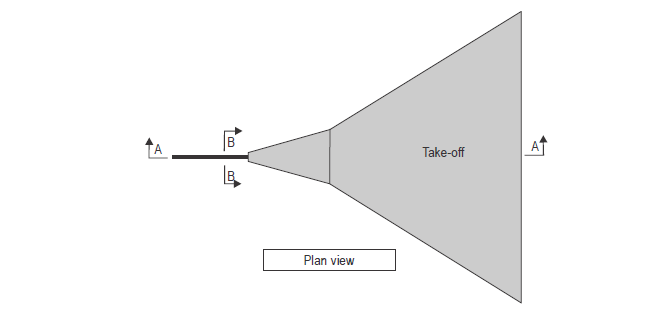
Figure 2: Plan view of the Instrument Departure Surface, as can be found in the ICAO State Letter [3].
How can Pager Power help?
Pager Power has a model for the new ICAO OLS as it is set out in [2]. Pager Power is able to undertake initial modelling of these surfaces and can offer initial consultation to developers and airports who require clarity on the new rules that are to be brought into force, having over 20 years of experience in the aviation sector.
More on Pager Power’s new ICAO OLS Modelling can be found here.
About Pager Power
Pager Power undertakes technical assessments for developers of renewable energy projects and tall buildings worldwide. For more information about what we do, please get in touch.
References
[1] Pager Power modelling output, visualised in Google Earth.
[2] ICAO State Letter (Reference AN 4/1.1.58-23/33)
[3] ICAO, Annex 14 to the Convention on International Civil Aviation, Ninth Edition, July 2022 Volume I
[4] CAA CAP 168, Licensing of Aerodromes
Thumbnail image accreditation: Jan Rossolino (May 2021) from Unsplash.com. Last accessed on 14th January 2025. Available at: https://unsplash.com/photos/white-and-blue-airplane-flying-under-blue-sky-during-daytime-bqNTyyOqPD8
post contents
About the Author: Harry Watson
Latest News
Dutch Temporary Framework for Solar near Airports
In March 2025, glare from a nearby solar farm temporarily [...]

Onward 2030 Work Package 3: The Future of Wind Mitigation
Onward 2030 Work Package 3 (WP3) has been produced with [...]

What is Electronic Conspicuity, and How Could it Unlock Onshore Wind?
Electronic Conspicuity (or EC) is a term used to describe [...]


