Visual Circuits and Glint and Glare Overview
 – news article – holding image")
Overview
The visual circuit is a specified path in which an aircraft flies visually in the airspace around an aerodrome. These are utilised at aerodromes all across the UK and internationally and come in various shapes and sizes. Visual circuits are becoming a more common receptor for assessment within glint and glare analysis for particular aerodromes, and therefore it is worthwhile explaining what they are and why they are important. The following article describes the visual circuit, why it is in place and how it may be assessed within a glint and glare assessment.
What is the Visual Circuit?
The visual circuit typically has three main uses, these are:
- It is a useful training procedure for learner pilots which inherently maintains close proximity to an aerodrome;
- It assists with the safe co-ordination of air traffic visually around an aerodrome, with the aim of reducing collision risk for arriving and departing aircraft;
- It is an almost standardised procedure that new and experienced pilots can use at most aerodromes.
The visual circuit is a way to ensure visual contact is maintained with an aerodrome. At each aerodrome, the circuit pattern may differ in width, length and altitude. They may use physical structures on the ground as reference points for ease of navigation e.g. a river or road, and they may be designed to avoid overflying populated areas.
Visual circuits are more commonly implemented at general aviation (GA) or military aerodromes. At larger licensed aerodromes (airports such as Heathrow and Gatwick), visual circuits are rarely used due to the safety risk of combining large movements of jet aircraft with smaller GA aircraft in a small area of airspace. Commercial jet aircraft also utilise radio navigation aids rather than relying on flying by sight.
The reason for a standardised circuit design (in shape) is for enhanced safety in the airspace around an aerodrome. It would not be suitable for pilots to simply co-ordinate themselves visually in a ‘free for all’ around the aerodrome, therefore having a set pattern means a pilot will more easily be able to navigate the airspace because they will know the typical locations in which other aircraft might be located.
How is the Visual Circuit Constructed?
Visual circuits are constructed relative to a runway’s orientation. Each runway can have two circuits on either side. As an example, the figure below shows a runway with the designation 09/27. This runway could have two circuits on either side of the runway, with aircraft being able to fly in either direction, which would be influenced by the wind direction. The direction of travel is identified by both the runway designation and the terms ‘left-hand’ or ‘right-hand’. The figure below shows a single circuit pattern and is the runway 09 right-hand/runway 27 left-hand circuit (the arrows denote the 09 right-hand circuit). This is because a pilot taking off on runway 09 would take-off on an initial bearing of 90 degrees and then only complete right-hand turns to fly the circuit. A pilot taking off on runway 27 would take-off on an initial bearing of 270 degrees and then only complete left-hand turns to fly the circuit. The circuit on the northern side of this runway would be the runway 09 left-hand/runway 27 right-hand circuit for the opposite reasons to those listed above.
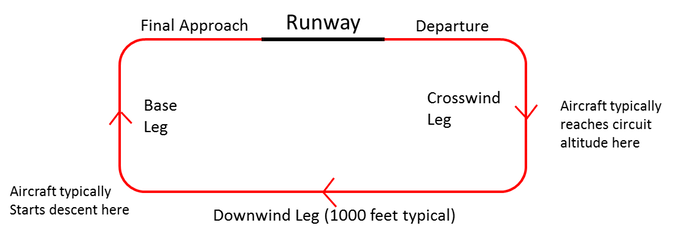
Figure 1: Typical circuit diagram
The typical visual circuit shown is constructed of five main parts, these are:
- Departure. A flight path parallel to and in the direction of the landing runway. An aircraft would be on the ascent on this leg;
- Crosswind leg. The aircraft may continues its ascent and level out at the maximum circuit altitude. This leg is at right angles to runway;
- Downwind leg. A long level flight path parallel to but in the opposite direction of the runway;
- Base leg. An aircraft will begin its descent on this leg at right angles to the final approach leg and the extended runway centerline;
- Final approach. A straight descending flight path in the direction of landing along the extended runway centerline from the base leg to the runway.
The precise way a circuit is flown varies from aerodrome to aerodrome, pilot to pilot and aircraft to aircraft, but they should follow the general pattern shown and fly at the relevant altitude. Whilst set paths are often stated either within aeronautical procedure websites/publications or specific aerodrome websites, a pilot will have to use the visual awareness to ensure the circuit is flown safely i.e. they maintain a safe separation distance from other aircraft and take alternate actions in emergency situations.
A typical circuit may have the following characteristics:
- Circuit altitude of 800ft (243.84m) or 1,000ft (304.8m) above the lowest runway threshold;
- The circuit originates and terminates at the runway ends [1];
- The circuit is typically flown with an ascent and descent angle of approximately 5°.
It is typically assumed that aircraft reach the maximum altitude of the circuit on the base leg however this may depend on the aircraft and the length of the departure leg of the circuit.
The circuit width will vary however a width of 1 nautical mile (nm) is typical.
How is the Visual Circuit Assessed with Respect to Glint and Glare?
Where the circuit dimensions are unknown, Pager Power assumes typical parameters. A circuit width of 1 nautical mile (nm) is typically modelled with a maximum altitude of 1,000ft. An ascent angle of 5 degrees means the aircraft reaches maximum altitude on the crosswind leg and begins the descent on the base leg. In total, Pager Power models 40 individual aircraft receptor locations that are equally spaced around a circuit from threshold to threshold. This process is used to provide an accurate indication of where glare from a solar development may occur and assist with the operational assessment. The figure below shows an example circuit diagram for Norwich Airport. It has a 1nm width and a 5-degree angle of ascent and descent. Each point would be assessed as a 3D point in space relative to a reflective solar panel area.
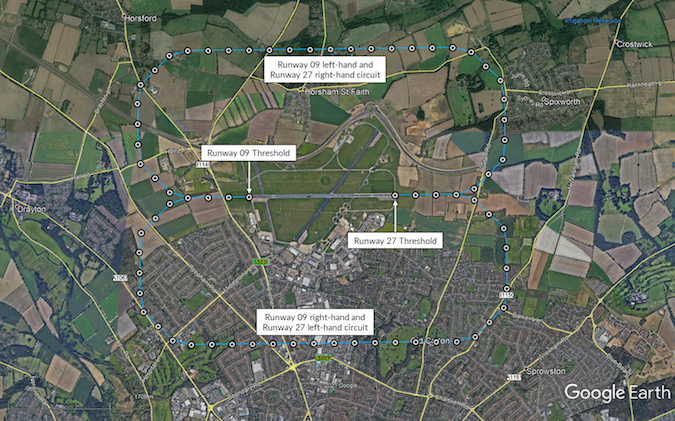
Example circuit diagram for Norwich Airport [2]
The criteria for impact categorisation are not as universally standardised for aircraft in the circuit as they are for more ‘conventional’ receptors such as pilots on final approach or air traffic controllers in the tower. Evaluation of the level of effect should therefore be made with reference to criteria for related receptors, first principles and operational considerations at the specific aerodrome. To this end, Pager Power considers:
- Which points within the circuit are potentially affected by glare;
- The glare intensity – although the criteria for acceptability are less stringent for aircraft in the circuit than aircraft on final approach;
- The relative position and visibility of the reflecting panels relative to the circuit path;
- Reflectors in the existing environment;
- The level of effect relative to direct sunlight.
- Operational procedures or restrictions specific to the aerodrome, if known.
Based on the above, the acceptability of any predicted glare is determined accordingly, usually in close co-ordination with the aerodrome safeguarding team.
Conclusions and Recommendations
The visual circuit is a well-known procedure flown by pilots all over the world. It has been designed to maximise safety by reducing collision risk and to ensure each pilot knows the typical procedure.
The visual circuit may be a consideration when assessing the impact of solar development in the vicinity of an aerodrome. The requirement for assessment varies from aerodrome to aerodrome and therefore consultation is key to find out whether the circuits are a key receptor. The impact of glare upon a circuit should be assessed geometrically, operationally and visually, and consultation with the aerodrome might be required to understand their specific operations. The most important aviation receptors for glare remain the ATC Tower and the last two miles of the final approach path, in accordance with industry best practice.
References
[1] Runway thresholds.[2] Google Earth image. © 2021 Google.Thumbnail image accreditation: Brent Cox (August 2017) from Unsplash.com. Last accessed on 16 July 2021. Available at: https://unsplash.com/photos/gxvYZk4Fwjk
post contents
About the Author: Danny Scrivener
Latest News
Dutch Temporary Framework for Solar near Airports
In March 2025, glare from a nearby solar farm temporarily [...]

Onward 2030 Work Package 3: The Future of Wind Mitigation
Onward 2030 Work Package 3 (WP3) has been produced with [...]

What is Electronic Conspicuity, and How Could it Unlock Onshore Wind?
Electronic Conspicuity (or EC) is a term used to describe [...]


