Solar Glare Intensity: What is the Bidirectional Reflectance Distribution Function (BRDF)?
Last Updated: September 16, 2026
Share:
When undertaking glint and glare assessments, it is often necessary to predict not only whether solar glare is geometrically possible, but also the glare intensity: how intense any instance of glare will be.
Glare Intensity Calculation: What has changed recently?
Glare Intensity has been relevant when assessing sites in close proximity to airports for almost as long as glint and glare assessments have been required [1]. In the past couple of years, however, it has become an increasingly common requirement in regard to road and railway receptors, with multiple authorities both in the UK and in Europe [2] now requiring it.
There is also an increase in the variety of reflective materials that need to be assessed. This has arisen partly due to an increase in reflective materials being used in construction, and partly due to an increase in the number and type of building projects in which glare intensity calculations are required.
The result of both of these recent developments is that there are many more situations in which glare intensity calculations, and therefore the inputs for these calculations, are required where the materials involved are not solar panels. One input that is commonly required is the surface reflectivity.
Glare Intensity Methods and Surface Reflectivity
It should first be noted that there are three methods commonly used for determining glare intensity:
- The FAA/Sandia method [3], which uses calculations of the subtended beam angle and irradiance at the observer’s retina to establish whether a glare spot is predicted to present an after-image.
- Luminance, a measure of the intensity of light at its source, which is commonly used in Europe.
- Veiling luminance, which is assessed using the glare protractor, developed by David N Hassall in accordance with the earlier Holladay formula. [4]
These vary in their applicability, methods, outputs and acceptability criteria, but they all factor the properties of the Sun and the properties of the reflective surface into their calculations.
The surface reflectivity is commonly expressed as a single percentage value. A surface reflectance of 10%, for instance, would be used to indicate that 10% of the light energy incident from the Sun is reflected towards the observer, and so the reflected sunlight ray would be taken to have 10% of the energy of the incident ray.
This surface reflectivity often varies depending on the incidence angle of the Sun on the surface. It is typically the case for solar panels, for instance, that where the sun beam hits the panel head on, the surface reflectivity is low, often just a couple of percent, but that this can increase to up to 50% or more for glancing reflections.
Surface Reflectivity Data Requirements
For solar panels, extensive research has been undertaken on surface reflectance by bodies including Sandia, and generic surface reflectivity profiles are readily accessible in glint and glare prediction software.
When assessing glint and glare from surfaces that are not solar panels, there is often less research available on their reflectivity as they have historically been seen as being less relevant. Any study into their lighting is more likely to be focused on the aesthetic properties of a surface for architectural design purposes, rather than on the reflectance profile for solar glare calculation purposes.
One such value that is often quoted for these sorts of surfaces is gloss, typically quoted in gloss units. This measure, though it can be used as a comparison for amounts of light emanating from different surfaces, does not provide sufficient information for use in the context of glint and glare.
Where there is a lack of information, it is possible in the first instance to use known existing reflectivity profiles alongside qualitative judgement to determine whether glare intensity is likely to be problematic. It is highly recommended, however, that specific information be sought on the reflective properties of a given surface, given the differences that can arise between surfaces. This is of particular importance in cases where the results are close to a borderline of acceptability.
Obtaining Surface Reflectivity: The Bidirectional Reflectance Distribution Function
Surface reflectance for the purposes of glint and glare cannot be determined based on calculation alone. It instead has to be determined experimentally in laboratory conditions by obtaining a Bidirectional Reflectance Distribution Function (BRDF) for the surface, which can then be converted to a surface reflectivity value pertinent to solar glint and glare assessments.
Experiment
The experimental setup typically consists of a light source, the reflecting material and a light sensor. [5] The light sensor measures the intensity of the reflected beam and needs to capture the amount of light reflected at a range of azimuth and elevation angles. This is all typically undertaken in a laboratory using a Goniophotometer, which will measure the reflectivity across all relevant angles in order to obtain the BRDF of the surface.
Output and Calculation
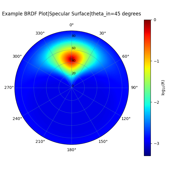 BRDF plot for a hypothetical specular reflecting surface, assuming an incident azimuth angle of 180 degrees and elevation of 45 degrees. The reflectance density function is high immediately surrounding the reflected ray and low elsewhere. [6]
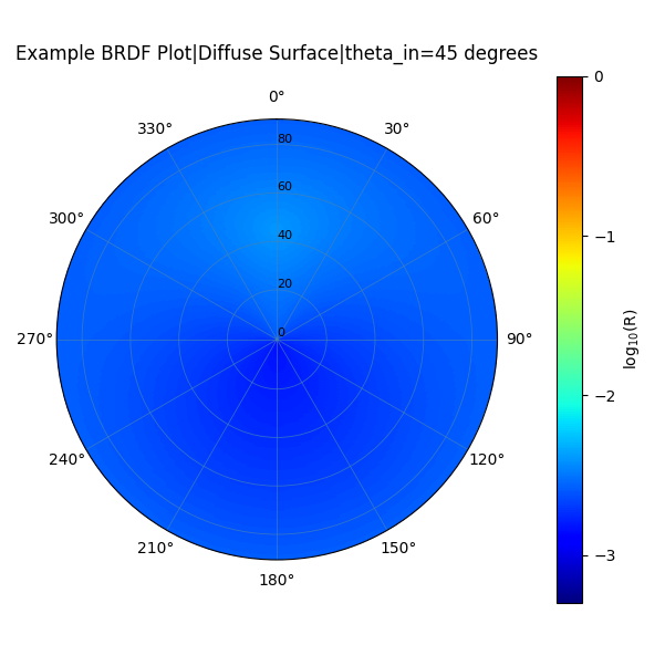 BRDF plot for a hypothetical diffuse reflecting surface, assuming an incident azimuth angle of 180 degrees and elevation of 45 degrees. The reflectance density function is only slightly higher on the direct path of the reflected beam. [6]
An output is then given that generally consists of a diagram showing the reflection densities at different reflectance angles. For a specular reflection, these reflection density values will be high among a small number of points surrounding the expected trajectory of a reflected beam; for a diffuse reflection, the reflection density values will be more uniform across the whole reflecting sphere.
This then needs to be translated into a reflectance value for use in a glint and glare assessment, which is done by integrating (summing) the reflection density values across the relevant directions to determine what proportion of the incoming light is reflected in those directions. For the purposes of assessing solar glint and glare, a cone of radius 3 degrees around the geometrically reflected beam is taken, and the density function is integrated with respect to solid angle within this cone to obtain the reflectance value of the surface.
How Does Surface Reflectivity Affect Glint and Glare Assessments?
The obtained surface reflectivity value can finally be fed into the glare intensity calculation. The effect of the aforementioned cone is that a particular surface can simultaneously reflect a smaller overall proportion of incident light, while still possessing a higher reflectivity value and producing more intense glare, if it is specular.
It is for this reason that accurate data should be supplied not only of the overall surface reflectance, but also on the spread of any reflected light, in order to obtain the most accurate assessment of glare intensity. In many cases however, this data is not available. In this instance, any data that is available should be used in conjunction with expert opinion to draw a valid conclusion.
How Pager Power can Help
Pager Power has undertaken over 1900 glint and glare assessments in the UK and worldwide. This includes geometric glare modelling and glare intensity modelling for solar and building developments of any scale for a wide range of developers. This includes private residents, commercial developers, planning authorities, or anyone else looking for impartial, expert advice. If you have any questions about your project, please do get in touch.
References
[1] FAA. Interim Policy, FAA Review of Solar Energy System Projects on Federally Obligated Airports. 2013
[2] DE Fernstraßen-Bundesamt (FBA). Key points paper on photovoltaics: Glare effects and glare assessments. November 2025.
[3] Clifford K. Ho, Cianan A. Sims, Julius Yellowhair, and Evan Bush. Solar Glare Hazard Analysis Tool (SGHAT) Technical Reference Manual Version 6. March 2015.
[4] David NH Hassall (1991) Reflectivity, Dealing with Rogue Solar Reflections – ISBN 064607086
[5] Surface Optics. BSDF, BRDF and BTDF – A Review of Measurement Approaches. https://surfaceoptics.com/bsdf-brdf-and-btdf-a-review-of-measurement-approaches/
[6] Pager Power modelling using Matplotlib
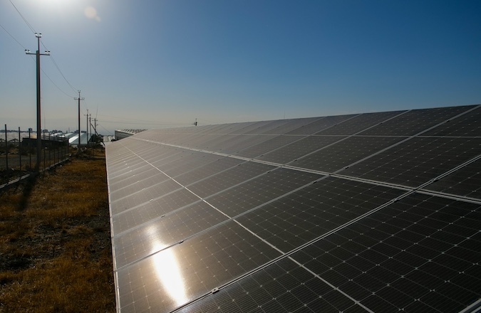
Image accreditation: Hrant Khachatryan (October 20222) from Unsplash.com+. Last accessed on 16 September 2026. Available at: https://unsplash.com/photos/the-sun-shines-brightly-on-a-solar-panel-qDC53De3w_Y
post contents
About the Author: Harry Watson