Obstacle Limitation Surfaces
 – news article – 20171024 DS OLS Introduction")
Last Updated: June 9, 2015
Categories:
Share:
What Are Obstacle Limitation Surfaces?
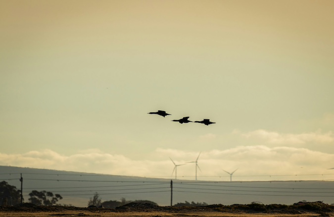
The UK has [1] 129 licensed civil aerodromes (and even more unlicensed aerodromes). In order to protect aircraft against potential collision risk, it is necessary to implement rules regarding tall structures surrounding aerodromes.
In the UK, this is done via ‘Obstacle Limitation Surfaces’, which are imaginary planes defined [2] in 3D around the aerodrome which must not be infringed. This is illustrated in the figure below.
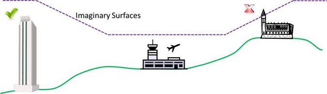
Figure 1: Relevance of Obstacle Limitation Surfaces.
This article gives an overview of the most important Obstacle Limitation Surfaces with regard to wind turbines and commercial building developments.
The Approach Surface
An approach surface is established for each runway direction intended to be used for the landing of aircraft. It is a wedge shaped surface that slopes upwards in stages from the end of the runway. The details of the dimensions and the angles are dependent on technical runway details not discussed within this article. The examples presented here are based on a long runway such as those at London Heathrow, London Gatwick and London Stansted.
The figure below shows a plan view of an approach surface – not drawn to scale.
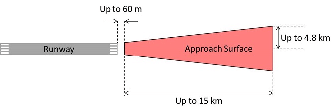
Figure 2: Plan view of an approach surface.
The figure below shows a profile of an approach surface – not drawn to scale.
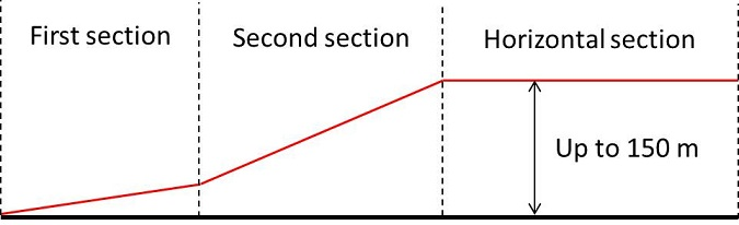
Figure 3: Profile view of an approach surface.
The Take-Off Climb Surface
A take-off climb surface is established for each runway direction intended to be used for take-off. The figure below shows a plan view of a take-off climb surface – not drawn to scale.
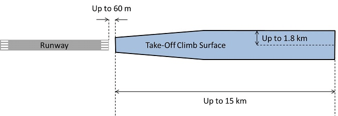
Figure 4: Plan view of a take-off climb surface.
The take-off climb surface slopes upwards away from the runway at a uniform angle from start to finish.
The Inner Horizontal Surface
The inner horizontal surface is an imaginary flat plane that is established around every licensed aerodrome. It can be circular or ‘racetrack’ shaped depending on the technical details of the runway.
The figure below shows a plan view of an inner horizontal surface – not drawn to scale.
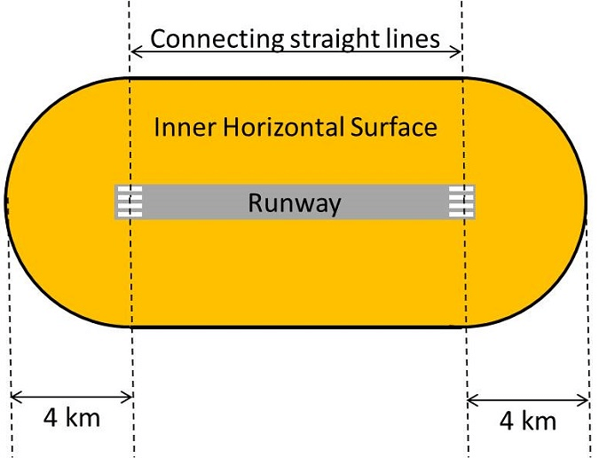
Figure 5: Plan view of an inner horizontal surface.
The height of the surface is continuous and is defined relative to the lowest runway threshold at the aerodrome.
The Conical Surface
A conical surface extends outwards from the edge of the inner horizontal surface described above. The figure below shows a plan view of an inner horizontal surface – not drawn to scale.
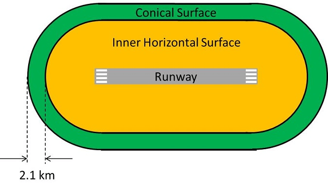
Figure 6: Plan view of a conical surface.
The conical surface slopes upwards away from the runway at a uniform angle from start to finish.
The Outer Horizontal Surface
The outer horizontal surface is an imaginary circular flat plane that is established around large aerodromes.
The figure below shows a plan view of an outer horizontal surface – not drawn to scale.
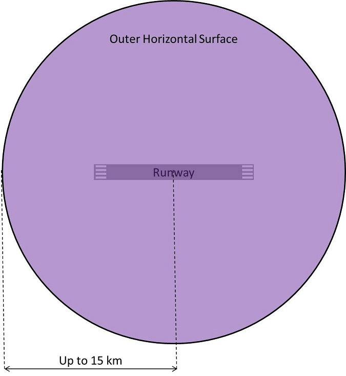
Figure 7: Plan view of an outer horizontal surface.
The height of the outer horizontal surface is continuous and defined relative to the runway thresholds.
Other Surfaces
There are other slightly more complicated surfaces, which are constructed in close proximity to the runway. These are not discussed at length here; they are rarely relevant for wind turbines or building developments.
Conclusions
Failing to consider these surfaces can jeopardise a wind development or a building development. It is important to understand the Obstacle Limitation Surfaces for aerodromes within approximately 15 – 20 km of any proposed tall structures.
There are examples of developments that breach Obstacle Limitation Surfaces. A breach is not necessarily a project show-stopper, however understanding any potential breaches and subsequent engagement with the relevant aerodromes is advisable to maximise a project’s chance of success.
References
[1] UK AIP accessed June 2015.
[2] Civil Aviation Publication (CAP) 168 (www.caa.co.uk), Civil Aviation Authority (CAA), most recent issue at the time of writing is dated 07/03/14
post contents
About the Author: Mike
Latest News
US Continues to Build Out Solar Capacity
Earlier this month, the Solar Energy Industries Association (SEIA) released [...]
China’s Airborne Wind Turbines
In early 2026, China successfully developed an airborne wind turbine [...]
Shadow Flicker Assessments for Wind Turbines: A 2026 Update
Shadow flicker is the effect of rotating turbine blades, causing [...]


