The Ministry of Defense (MOD) and the Military Aviation Authority (MAA) have recently issued Regulatory Article 3522 [2], which provides guidance on the design and safeguarding of Vertical Landing Pads (VLP). These square pads were originally brought in at RAF Marham in 2018 to allow F-35B aircraft to land on an area much smaller than that of a conventional runway. The document [2] defines the expected layout of the pads before outlining the dimensions of a set of Obstacle Limitation Surfaces (OLS) intended to safeguard the pads.
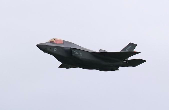
Figure 1: Lockheed Martin F-35B, capable of undertaking vertical landings. [1]
The Ministry of Defence (MOD) and the Military Aviation Authority (MAA) have recently issued Regulatory Article 3522 [2], which provides guidance on the design and safeguarding of Vertical Landing Pads (VLP). These square pads were originally brought in at RAF Marham in 2018 to allow F-35B aircraft to land on an area much smaller than that of a conventional runway. The document [2] defines the expected layout of the pads before outlining the dimensions of a set of Obstacle Limitation Surfaces (OLS) intended to safeguard the pads.
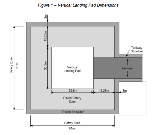
A VLP has standardised dimensions both for the pad itself and the safety zone which surrounds it. The VLP itself is a square measuring 30.5 metres by 30.5 metres and this is surrounded by a Paved Safety Zone of 15.25 metres and a Paved Shoulder of 3 metres on all sides. This gives an overall dimension of the VLP, Paved Safety Zone and Paved Shoulder of 67 by 67 metres. The VLP is then connected to the rest of the aerodrome by a taxiway.
Figure 2: A plan view of the required layout of a Vertical Landing Pad. This shows the Vertical Landing Pad, Paved Safety Zone and Paved Shoulder, along with their respective dimensions. [2]
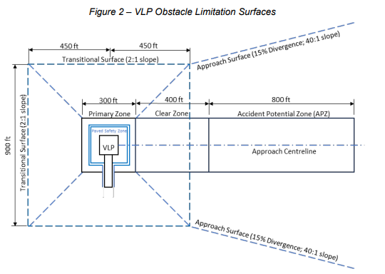
Various OLS have been established for the VLP. These are somewhat reminiscent of existing rules which have been in place for fixed wing aircraft and helicopters as far back as the 1950s. The genealogy of the Primary Zone, Clear Zone and Accident Prevention Zone (APZ) can be traced quite clearly to the Obstacle Free Zones which safeguard runways, in that they all should be free of obstacles, with only frangible obstacles excepted in the case of the APZ. The Primary Zone and Clear Zone have further requirements beyond their obstacle free status, with rough grading required to “minimize damage to the Aircraft in the event of an emergency landing and to encourage drainage and avoid standing water”. This is important given the sensitivity of the vertical landings that are expected to be carried out.
Other surfaces do admit the construction of buildings underneath them, namely the Transitional, Approach and Inner Horizontal Surface (IHS), which serve the same purpose as their counterparts for runways. The Transitional Surface starts at the edge of the Primary Zone and, in common with the transitional surface for helicopters [3,4], it has a gradient of 50%. This surface extends to a height of 45 metres/150 feet above ground level, where it meets (in the direction of the approach) the Inner Horizontal Surface and the Approach Surface.
The Approach Surface begins at the top of the transitional surface in the direction of approach, with its inner width being 900 feet. It extends outwards at a 2.5% slope and 15% divergence until it reaches 500 feet above ground level. Note that the 2.5% slope and 15% divergence figures are the same values as for the second (outer) section of the approach surface on code 3 and 4 instrument runways [5].
Figure 3: A plan view of the OLS of a VLP. This shows the Primary Zone, the Clear Zone and the Accident Potential Zone where objects are typically not permitted. It also shows the Transitional Surface and Approach Surface where the height of obstructions is limited. Note that the Inner Horizontal Surface is not shown on the diagram. [2]
The IHS sits at an elevation 45 metres above that of the VLP and extends to a radius of 6000 feet (1829 metres) on a 180 degree semicircle towards the origin of the approach. Unlike the runway case, this does not span a full circle unless the VLP happens to have approaches from multiple directions which would cause the IHS for each of them to combine to form a circle.
It is noted, however, that “When the VLP is on or adjacent to an Aerodrome, the inner horizontal surface may be established to match the Aerodrome’s inner horizontal surface.” and that furthermore “When the VLP is located within the boundaries of an existing Aerodrome and the OLS of the two facilities overlap, the VLP transitional surface elevation will extend to meet the existing inner horizontal surface elevation of the Aerodrome.” At the moment these VLPs are present only at RAF Marham which has two runways, 01/19 and 05/23, in addition to them [6].
It seems that details on the IHS exist at this point primarily to future-proof the regulation since no such surface is applicable in practice, with the existing IHS at Marham instead taking precedence, serving its purpose as a horizontal surface for the VLPs present and an upper bound to the transitional surfaces.
By the same token, the guidance states that “The VLP OLS requirements may be omitted in part or full where existing Aerodrome OLS meet or exceed the obstacle clearance requirements defined by the VLP OLS presented in this Regulation.” In the case of a VLP sited on an aerodrome, it seems difficult to determine instances in which off-aerodrome obstacles would breach a VLP but not a conventional runway OLS. Whilst certain peculiarities exist, particularly (for instance) with code 1 and 2 non instrument runways which have a far smaller IHS (2500m against the more usual 4000m) [5], the VLP would tend to be a far greater consideration for obstacles planned on the aerodrome in the immediate vicinity of the VLP.
How can Pager Power help?
Pager Power has developed a model for the new VLP OLS as it is set out in [2] and is able to assess developments against this criteria alongside other safeguarding criteria including OLS for conventional runways, Instrument Flight Procedures, Building Restricted Areas for navigation aids and impact on radar signals.
More on Pager Power’s aviation services can be found, here.
About Pager Power
Pager Power undertakes technical assessments for developers of renewable energy projects and tall buildings worldwide. For more information about what we do, please get in touch with one of our experts today.
References
[1] Tony Hisgett, Creative Commons Attribution 2.0 Generic license, Accessed at: https://commons.wikimedia.org/wiki/File:F-35B_Lightning_16_(53786000822).jpg
[2] MOD and MAA. RA 3522: permanent fixed wing aerodrome – vertical landing pads. Available at: https://www.gov.uk/government/publications/regulatory-article-ra-3522-permanent-fixed-wing-aerodrome-vertical-landing-pads. Accessed October 2024.
[3] ICAO Annex 14 – Aerodromes, Volume II. Fifth Edition July 2020.
[4] CAA. CAP 1264: Standards for Helicopter Landing Areas at Hospitals. Available at: https://www.gov.uk/government/publications/regulatory-article-ra-3512-permanent-fixed-wing-aerodrome-obstacle-environment. Accessed October 2024.
[5] MOD and MAA. RA 3512: permanent fixed wing aerodrome: obstacle environment. https://www.gov.uk/government/publications/regulatory-article-ra-3512-permanent-fixed-wing-aerodrome-obstacle-environment. Accessed October 2024.
[6] UK Mil AIP. EGYM – MARHAM. Combined Textual Data and Charts. Available at: https://www.aidu.mod.uk/aip/aipVolumes.html#. Accessed October 2024.

