CNS Safeguarding Series: ICAO Eur Doc 015 Building Restricted Areas

The European Guidance Material on Managing Building Restricted Areas [1], referred to in short as ICAO Eur Doc 015, provides a methodology for determining whether proposed development is likely to create signal interference for CNS (Communication, Navigation and Surveillance) equipment. Obstructions are assessed against invisible 3D surfaces. The guidance recommends that obstructions that do not breach the surfaces are to be approved. Obstructions that breach the surfaces are expected to require more detailed analysis to determine the nature of any interference caused to CNS signals.
What is a BRA?
Each piece of CNS equipment present at an aerodrome has a role to fulfil with regard to the successful navigation of aircraft into and out of the aerodrome. It therefore follows that this equipment must be able to communicate clearly with aircraft, and that obstructions must not interfere with signals from any of the aids. To this end, each piece of equipment has a Building Restricted Area (BRA) centred on it. Each BRA is formed of multiple invisible 3D Surfaces to cover different regions relative to the navigation aid in question, and they come in two forms, directional and omnidirectional.
Directional BRAs for CNS Equipment
Directional BRAs cover CNS equipment that is intended to primarily communicate with aircraft which are at a specific bearing from a navigation aid. Examples of navigation aids that have associated directional BRAs include ILS (Instrument Landing System) localiser and glide path equipment. These aids have the role of guiding aircraft into landing on a particular runway bearing, with aircraft requiring such guidance being specifically on the final approach path and therefore maintaining (almost) a constant bearing relative to the navigation aid.
Directional BRAs consist of a sloped sector of a circle whose direction is centred on the expected relative direction of the aircraft from the navigation aid. This is augmented by a series of horizontal rectangular surfaces near to the navigation aid, one of which ensures that the area in the immediate vicinity of the navigation aid is kept clear from any significant above ground obstacles.
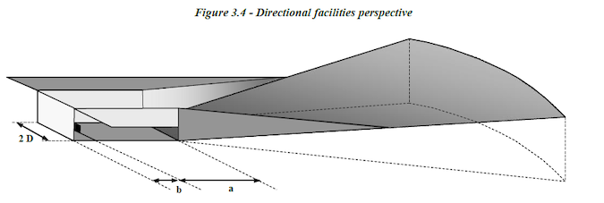
Figure 1: Perspective view of an example Directional BRA, as illustrated in [1].
The same shape of the BRA is shared across all directional navigation aids, but the exact dimensions vary. The BRA for an ILS Glide Path navigation aid has a splay of 10 degrees on each side, for instance, whereas the directional variation of a DME (Distance Measuring Equipment) has a splay of 40 degrees. In all cases, the sloped circle sector reaches a height of 70 metres above the ground elevation at the site of the navigation aid, and extends between 6 and 10 kilometres from it, depending on its type and the length of any associated runway.
Omnidirectional BRAs for CNS Equipment: Navigation Aids
Omnidirectional BRAs cover CNS equipment that is expected to communicate with aircraft in a range of directions. Examples of navigation aids falling into this category include DME and VOR (VHF Omnidirectional Range). These aids are used by aircraft to establish their distance and bearing respectively from the beacon in question. Aircraft flying instrument flight procedures will potentially need to be able to access this information from such a navigation aid from all directions, and so obstructions are commensurately restricted more consistently across different directions.
Omnidirectional BRAs typically consist of a small circle at ground level permitting no significant obstructions above ground level in the immediate vicinity of the navigation aid. There is then a cone which extends out to a given distance and height, and in some cases, a horizontal surface surrounding this.
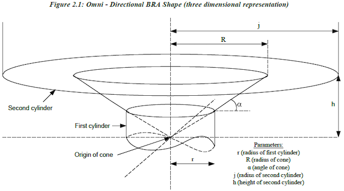
Figure 2: Perspective view of an example Omnidirectional BRA, as illustrated in [1].
In much the same way as with the Directional BRAs, the Omnidirectional BRAs all follow this general shape, with some dimensions varying between the navigation aids. For example, the BRAs of CVOR (Conventional VHF Omnidirectional Range), DVOR (Doppler VHF Omnidirectional Range) and Direction Finder facilities have a horizontal surface outside the cone, but the BRAs of other types of omni-directional navigation facilities do not. A radius of 3000 metres is applied fairly uniformly to the cone, with the exception of 1000 metres for the BRA of an NDB, and 200 metres in the case of the BRA of a Marker. There is far more variance in the gradients of the conical sections of Omnidirectional BRAs. This is 1 degree for DME, CVOR, DVOR and Direction Finder, but can be as much as 20 degrees for other navigation aids.
Omnidirectional BRAs for CNS Equipment: Communication and Surveillance Facilities
The same general shape of the Omnidirectional BRAs can be applied to the safeguarding of Communication and Surveillance facilities. Communication facilities- including VHF transmitters and receivers- have a slightly narrower cone at 2000 metres radius, with the same 1 degree gradient as the DME, CVOR, DVOR and Direction finder navigation aids. Surveillance facilities, including PSR (Primary Surveillance Radar) and SSR (Secondary Surveillance Radar), have a wider and shallower cone in their BRA: this extends to 15 kilometres from the base of the radar, but at a 0.25 degree gradient. At 15 kilometres, these BRAs have the largest radius of all those defined in ICAO Eur Doc 015.
How Pager Power can help
Pager Power has bespoke modelling software which can be used to model the safeguarding surfaces (BRAs) specified in ICAO Eur Doc 015. Our experts can model whether a proposed development breaches these surfaces, while engaging with the relevant stakeholders and providing high-quality support throughout the lifetime of your project. For support, please contact us.
Further Reading
Part 3 Navigation https://www.pagerpower.com/aviation/cns-equipment-deep-dive-part-3-navigation/
Part 2 Communications https://www.pagerpower.com/aviation/cns-equipment-deep-dive-part-2-communications/
Part 1 Introduction https://www.pagerpower.com/aviation/introducing-cns-equipment-deep-dive/
https://www.pagerpower.com/news/cns-safeguarding-series-icao-eur-doc-015-vs-cap-670/
References
[1] ICAO. European Guidance Material on Managing Building Restricted Areas. Third Edition, November 2015.
Featured Image: A radar tower at Heathrow Airport Copyright © 2007 David Monniaux on Wikimedia Commons CC-BY-SA 3.0 – https://commons.wikimedia.org/wiki/File:Heathrow_Airport_radar_tower_P1180333.jpg
post contents
About the Author: Harry Watson
Latest News

US Continues to Build Out Solar Capacity
Earlier this month, the Solar Energy Industries Association (SEIA) released [...]

China’s Airborne Wind Turbines
In early 2026, China successfully developed an airborne wind turbine [...]

Shadow Flicker Assessments for Wind Turbines: A 2026 Update
Shadow flicker is the effect of rotating turbine blades, causing [...]


