Overview
We have recently completed a number of television reception surveys for large buildings in cities like London and Manchester, as well as working on a number planning applications for wind farms nationally. We therefore wanted to provide you with an update to our previous article highlighting the reception survey process and the kit we use, complemented with some photos taken on a Spring day in the East Anglian countryside.
The survey vehicle
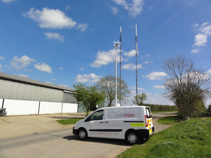
Figure 1: Custom Toyota Proace
The Pager Power survey vehicle is a custom Toyota Proace panel van with standard wheelbase and height. The Proace has a 2L diesel engine providing 128BHP. This particular engine is the most efficient in the range giving a combined driving (mpg) of 44.1 whilst also producing the lowest CO2 emissions (168 g/km) [1].
The photo above shows the survey vehicle and the Sudbury television transmitter.
The signal analyser
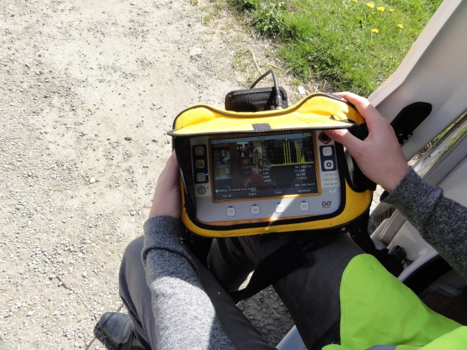
Figure 2: Promax signal analyser
We use a Promax HD Ranger + universal analyser which can decode standard and high definition terrestrial television channels as well as digital and analogue radio. The analyser can also decode many other signal types however surveying the aforementioned signal types is most common.
The analyser provides data on signal strength and stability. We can also review the Bit Error Rate, picture and sound quality.
In the image above you can see the decoded picture as well as the signal strength graph in the top right and key information in the bottom right. The analyser is plugged into the aerial located on the extendable mast.
The mast and aerial
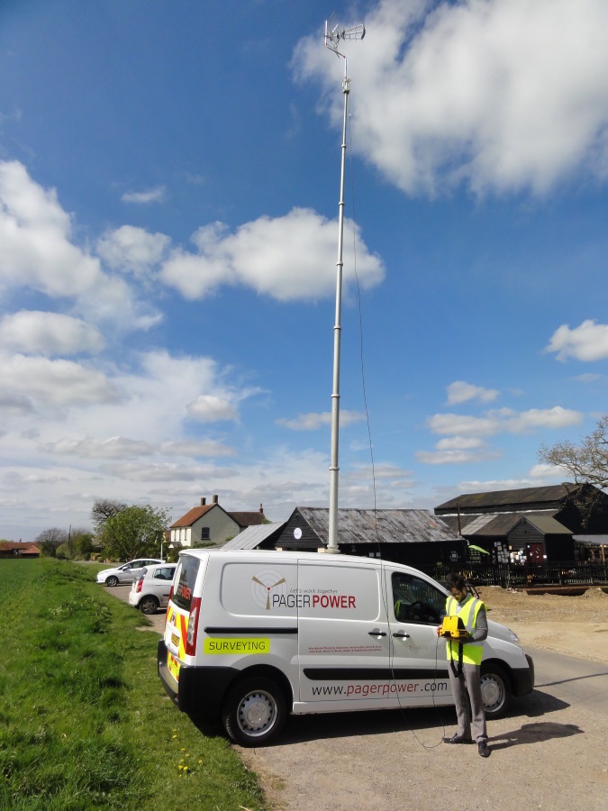
Figure 3: Pneumatic mast and wideband UHF aerial
Our survey vehicle has been fitted with an extendable 10m pneumatic mast where we place the wideband UHF aerial capable of measuring many signal types. A cable then connects the signal analyser to the aerial. A mast with a maximum height of 10m above ground level [2] was selected because this is the height recommend by Ofcom.
The surveyor
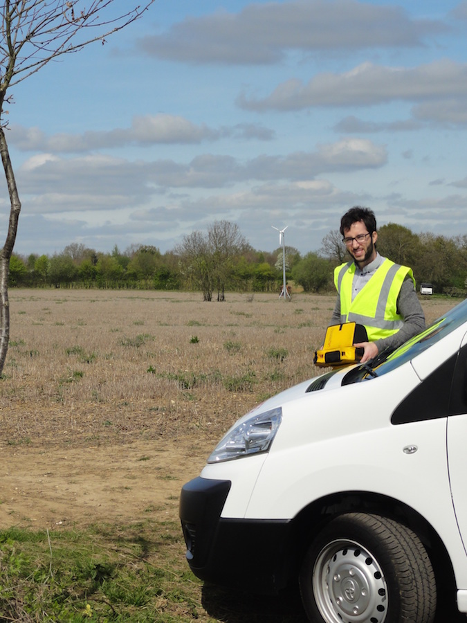
Figure 4: Pneumatic mast and wideband UHF aerial
Each surveyor is professionally trained with the survey vehicle and signal analyser to ensure the safety and accurate results whilst surveying.
The photograph above shows the surveyor (me) getting the Promax analyser ready for a signal reading. In the background is a domestic wind turbine [3].
Conclusions
We hope that this article has given you more of an insight to our surveying process and the kit we use.
If you require a signal receptions survey please get in touch and we’d be happy to discuss your project.
References
[1] Source: Toyota Proace model guide.
[2] This is the height defined by Ofcom when designing a terrestrial television system.
[3] Note that wind turbines requiring a television reception survey as part of planning permission are typically much larger than the wind turbine shown in the photograph.


